
GPIOs and Go

Go Advent, Dec. 22, 2018
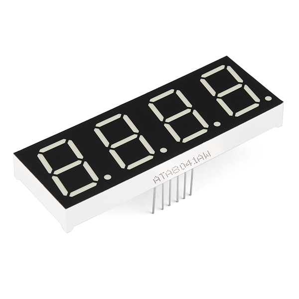
Recently, I decided that I needed a small heads up display for import things I kept forgetting, like the time until an event started or number of unread emails in my inbox. I wanted the display to be simple and bright so it would really catch my eye. I naturally started to look at seven segment displays. Four digit, seven segment displays are available in most hobby electronics stores and come in a variety of packages. What is most noticeable when comparing these packages is that the 12 pin, analog package is significantly cheaper than the packages with bus interfaces (UART, SPI, I2C, etc.) and less pins. I wasn’t using the majority of GPIOs on my Raspberry Pi Zero and being frugal, I decided to buy the analog package. What happened next was an exploration into how Go can quickly control GPIO pins to make the display actually work well.
Analog Seven Segment Displays
Seven segment displays are relics from another, more groovy, era, and while they do add a retro vibe to any project, they also are a very practical way to display information. You will often see them sold with I2C, SPI and UART buses that allow programmers to just send commands to control them. Driving the displays directly via GPIO pins is much trickier.
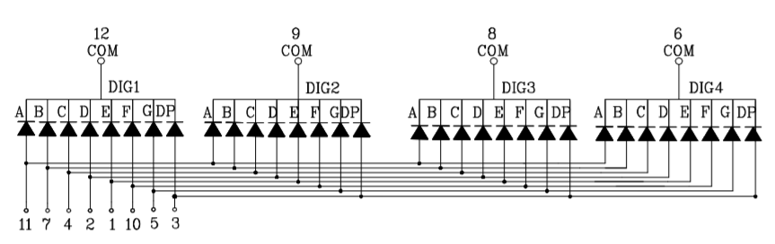
Above is the electrical diagram of the four digit, seven segment display I am using. It shows that pins 11,7,4,2,1,10,5, and 3 (the dot) are all tied to four LED anodes corresponding to positional segments (IE: pin 11 is in contact with all four top segments, pin 7 to all the top right segments, etc.) and that pins 12,9,8, and 6 are all tied to 8 LED cathodes corresponding to digits. Connecting these pins to the GPIOs of the Raspberry Pi Zero allows the segments to be lit by setting all the GPIOs to output mode and then either setting them high, where they act as 3.3V and current sources, or low , where they are < 0V, current sinks. This means that if a segment pin is high and a digit pin is low, then current will flow through that segment’s LED in that digit and light up. The problem with this is that unless you are going to show the same thing on all the digits, there is no built-in way to change individual digits while keeping the others lit (IE: If you have all the segment pins high and digit pins low, then there will be four eights with dots on the display).
1
|
Magic Smoke Warning - If you are making this circuit, put a current limiting resistor (300 Ohm should work) between GPIO sources and sinks. |
The way around this is to strobe the lights to give the appearance of individual digit control. There is enough control to light up one digit with the segments I want at a time (IE: lit digit pin is set low, all others are digit pins are high and the segment pins to whatever I want to show). If I cycle through lighting each digit up quickly with the segments I want, then the human eye will perceive that they are all lit up and unique. The YouTube below is a slow motion shot of an LED clock where you can actually see this strobing effect in action:
I now knew that I needed to control the GPIOs very quickly to drive the display. I wanted to use Go because I knew after I got the display working it be easier to leverage Go libraries for remote APIs and I just like programming in Go. With that in mind I began to look over how to efficiently interface Go with the Raspberry Pi’s GPIOs and control the display.
sysfs - built for comfort, not performance
the ‘normal’ GPIO control method
sysfs is the most common way to interact with GPIOs in Linux. It is a pseudo filesystem that allows for kernel object to be interacted with via userspace like files. In the case of GPIOs, there is a whole class of objects dedicated to them in /sys/class/gpio. Unless told by the Device Tree file (I’ll go into that more in the next section), the kernel will normally boot without exposing controls for specific GPIOs. You can create that hook by writing the number of the GPIO pin to the /sys/class/gpio/export file. This will then create the directory /sys/class/gpio/gpio<gpio#> and there will be two files of interest in it: direction and value. To set the GPIO to output mode, you need to write out to the direction file and then to control it you either write 0 or 1 to value. A very simple example is given below:
1 2 3 4 5 6 7 8 9 10 11 |
//We are concerned with GPIO 5 (physical pin mapping depends on kernel/board)
pin := "5"
//Export the GPIO kernel object for GPIO 5 to userspace via sysfs
ioutil.WriteFile("/sys/class/gpio/export", []byte(pin), 0644)
//Set GPIO 5 to output mode
ioutil.WriteFile("/sys/class/gpio/gpio"+pin+"/direction", []byte("out"), 0644)
//Open the value file
gpiof := os.Open("/sys/class/gpio/gpio"+pin+"/value")
defer gpiof.Close()
//Set GPIO 5 high
gpiof.Write([]byte("1")) |
dts and sysfs: gpio-leds
A more tailored solution can be achieved with sysfs by binding a special GPIO device driver to a specific GPIO via the Device Tree. The Device Tree is a file read by the kernel at boot that explains how to set pins in certain modes (pull up resistor, fuse, etc.) and associate them with a device driver. You can find the compiled version of the Device Tree as Flattened Device Tree Blob (dtb) files in the boot partition of the Raspbian OS image. The files are compiled from Device Tree Source (dts) files. For the Raspberry Pi Zero the primary dts file is ‘bcm2835-rpi-zero-w.dts’ and can be found in the Linux Kernel. The Device Tree syntax is a very simple JSON-like language that details nodes which convey properties about how to associate drivers to board pins and peripherals. An extremely detailed article about Device Tree files and the Raspberry Pi can be found here.
In regards to GPIOs used for LEDs, the dts files allow you to configure a GPIO more specifically for LED control with a special device driver called ‘gpio-led’. This is done in the dts file by creating a node and setting the compatible parameter to "gpio-leds" and then adding a sub-node with the gpio number specified. Most dts files for boards, including the Raspberry Pis, already have a node labeled leds that has this paramter set so you can just add the GPIOs you want configured as LEDs to it as subnodes. By adding the following to the ‘bcm2835-rpi-zero-w.dts’ file and compiling it into a new dtb, I can bind the gpio-led driver to GPIO 6:
1 2 3 4 5 |
&leds{
    TOPLED{
        gpios = <&gpios 6 GPIO_ACTIVE_HIGH>;
    }
} |
Once the Linux kernel reads this version of the dtb file, sysfs offers a new set of file-based interfaces located in /sys/class/leds/TOPLED at boot. The file of most concern is brightness that can be written to just like the value file before: 1 for high and 0 for low. An example of this is seen below. Unlike the generic GPIO sysfs interface, the GPIO is already exported and set to output.
1 2 3 4 5 |
//Open the brightness file for GPIO6, now named MYLED and associated with the gpio-led driver
gpiof := os.Open("/sys/class/leds/"+"/brightness")
defer gpiof.Close()
//Set high
gpiof.Write([]byte("1")) |
Result
Both of these methods lead to the same result, a GPIO output can be controlled by simply writing to a file. For simple GPIO interaction, like controlling an LED conveying status a user, these are great solutions. The main problem with them is that they are not fast. Calls have to go to a buffer, which is then interpreted by sysfs handlers which then send commands to the hardware driver that sets the correct GPIO registers. The periph project estimates that that sysfs incurs 10x to 72x performance cost. This seems like way to large of a delay to efficiently drive the display.
cgo - amazing, but not fast enough
For every hobby board there is almost always a corresponding GPIO C library. The most common GPIO C library for the Raspberry Pi Zero is wiringpi and it can be easily utilized by Go using cgo. Below is a simple example program demonstrating this:
1 2 3 4 5 6 7 8 9 10 11 12 13 14 15 |
package main /* #include <wiringPi.h> */ import "C" func main(){ gpionum := C.int(6) //Set the GPIO Mapping to use Raspberry Pi Labels C.wiringPiSetupGpio() //Set GPIO 6 to output mode C.pinMode(gpionum,C.OUPUT) //Set GPIO 6 high C.digitalWrite(gpionum,C.HIGH) } |
The problem with this approach is that while cgo is amazing at utilizing existing C code, it is not fast. Under the hood, cgo is a code generator and runtime engine, both of which are more concerned about making sure the interface works and less about speed. Most references suggests that there is a 20x-40x delay built into cgo calls.
Memeory Mapped GPIOs - a rocket w/o seatbelts
At this point I was considering using the periph Go library, which almost certainly would have given me the speed I needed, but I was too curious to rely on a higher level solution. To look for lower level solutions, I began looking at C methods for accessing GPIOs quickly and the top result was Memory Mapped I/O.
Memory Mapped I/O streamlines the processes of writing to board peripherals by allowing direct access, bypassing much of the logic the kernel uses to access them. All peripheral devices are accessible at a range of memory addresses. Given those parameters, memory mapping exposes that chunk of memory as if it was an array and all writes to the array are sent to those addresses automatically via syncing mechanisms. This is extremely useful, but it also means that you need to understand the registers exposed in the memory chunk in order to actually control the device. You no longer have the kernel making life easy.
| Address | Field Name | Description | Size | Read/Write |
|---|---|---|---|---|
| 0x7E200000 | GPFSEL0 | GPIO-Function-Select 0 | 32 | R/W |
| 0x7E200004 | GPFSEL1 | GPIO-Function-Select 1 | 32 | R/W |
| 0x7E200008 | GPFSEL2 | GPIO-Function-Select 2 | 32 | R/W |
| 0x7E20000C | GPFSEL3 | GPIO-Function-Select 3 | 32 | R/W |
| 0x7E200010 | GPFSEL4 | GPIO-Function-Select 4 | 32 | R/W |
| 0x7E200014 | GPFSEL5 | GPIO-Function-Select 5 | 32 | R/W |
| 0x7E20001C | GPSET0 | GPIO-Pin-Output-Set 0 | 32 | W |
| 0x7E200020 | GPSET1 | GPIO-Pin-Output-Set 1 | 32 | W |
| 0x7E200028 | GPCLR0 | GPIO-Pin-Output-Clear 0 | 32 | W |
| 0x7E20002C | GPCLR1 | GPIO-Pin-Output-Clear 1 | 32 | W |
Abridged version of Table 6-1 containing only the GPIO registers I care about
The BCM2835 ARM Peripherals, Section 6:GPIO, details the GPIO registers for the Raspberry Pi. Here are the takeaways:
- There is a typo in Table 6-1, the first row in the table is written twice
- The register are 32 bits long
- GPIO Function Select Registers (GPSELn) control the GPIOs Input/Output mode
- Each register is in charge of 10 GPIOs (GPFSEL0 -> GPIOS 0-9, GPFSEL1 -> 10-19, etc.)
- They are the first six registers
- They are readable and writable
- Each GPIO pin is configured via three bits in the register and their bits are in order of GPIO number. For the GPIO to be set as an output the corresponding bits must be 001. (IE: existing_value |= 0b001<<5 ==> set the 5th GPIO controlled by this register to output)
- The registers to set GPIOs high are the GPIO Pin Output Set Registers (GPSETn)
- There are two of them, GPSET0 is in charge of the first 32 GPIOs and GPSET1 has the rest
- They are the 7th and 8th register
- They are only writable
- Each GPIO has a bit and writing a 1 to it sets it high
- The registers to set GPIOs low are GPIO Pin Output Set Registers (GPCLRn)
- There are two of them, GPCLR0 is in charge of the first 32 GPIOs and GPCLR1 has the rest
- They are the 10th and 11th register
- They are only writable
- Each GPIO has a bit and writing a 1 to it sets it low
All of this can be summarized in three C macros below which appear in different forms often seen in Raspberry Pi code using Memory Mapped GPIOs. They assume that the gpio variable holds the pointer to the beginning of the GPIO registers via memory mapping. It also assumes that the gpio memory map is casted to a int32 array, which makes interfacing with the 32-bit registers much easier.
1 2 3 |
#define OUT_GPIO(g) *(gpio + ((g)/10)) |= (1<<(((g)%10)*3)) #define GPIO_SET *(gpio + 7) // sets bits which are 1 ignores bits which are 0 #define GPIO_CLR *(gpio + 10) // clears bits which are 1 ignores bits which are 0 |
Taking in all this information, I started to translate this to Go. First I needed to memory map the GPIO registers. syscall makes this very easy by having an Mmap method. It requires that I provide:
- File Descriptor - Mmap can be used for normal files as well as special memory mapped IO. To use it for GPIOs, I need to access a special file that represents all the memory accessible to the kernel. Normally this file is
/dev/membut Raspbian has an additional version of it that just gives access to the GPIOs called/dev/gpiomem, either should work. By opening this file and passing it toMmap, you can select ANY portion of memory. - Offset Value - The offset value, I need to get the memory offset for the GPIO registers in reference to where the file descriptor starts reading memory. This is calculated by taking the peripheral memory offset, which can be different for different Pi Models (Zero is 0x20000000), and then adding the GPIO offset, which is always 0x200000 for Rasbperry Pis.
- Memory Size - The memory size only needs to be 11 * 4 bytes because the highest addressed register we need access to is GPCLR0 at register 10 and each register is 4 bytes (32 bits); however, due to how memory mapping works we round this up to the nearest memory page size, 4*1024 bytes.
- Permissions- We need to read and write to the memory region, so we need to pass PROT_WRITE| PROT_READ
- Change Mode- We want writes to the array to be sent to hardware as soon as possible, so we set the change mode to MAP_SHARED
This can call be implemented with many magic values in Go as:
1 2 3 |
mmfile, _ = os.OpenFile("/dev/mem", os.O_RDWR, 0)
mmtmp, _ := syscall.Mmap(int(mmfile.Fd(), 0x20200000, 4 * 1024,
syscall.PROT_WRITE|syscall.PROT_READ, syscall.MAP_SHARED) |
The problem is that the slice returned by Mmap is of byte type and I’d prefer to work with int32 so that values match the register sizes. This is easy to do in C, but in Go this is trickier. I cannot move the internal array in the slice because it is the special memory mapped array, so I have to modify the slice header directly. I need to write a new slice header that will treat the underlying array as ints and also adjust the length and capacity for the data type size difference. The result is the helper function below:
1 2 3 4 5 6 7 8 9 10 11 12 13 14 15 16 |
//int is int32 on raspberyy pi zero
func bytesToInts(b []byte) []int {
    s := &reflect.SliceHeader{}
    s.Len = len(b) / 4
    s.Cap = len(b) / 4
    s.Data = (uintptr)(unsafe.Pointer(&b[0]))
    return *(*[]int)(unsafe.Pointer(s))

}

...
mmfile, _ = os.OpenFile("/dev/mem", os.O_RDWR, 0)
mmtmp, _ := syscall.Mmap(int(mmfile.Fd(), 0x20200000, 4 * 1024,
                        syscall.PROT_WRITE|syscall.PROT_READ, syscall.MAP_SHARED)
mm := bytesToInts(mmtmp)
... |
Ok, so I finally have the Go version of the int array that represents the GPIO registers as a memory mapped region. I now need to create the Go version of those C macros. Due to the similarities between C and Go, this was extremely easy:
1 2 3 4 5 6 7 8 9 10 11 12 13 14 15 16 17 |
//OutGpio mimics the macro below
//#define OUT_GPIO(g)   *(gpio.addr + ((g)/10)) |=  (1<<(((g)%10)*3))
func OutGpio(gpios []int,g int) {
    gpios[(g)/10] |= 1 << uint((g%10)*3)
}

//SetGpio mimics the c macro below
//#define GPIO_SET  *(gpio.addr + 7)  // sets   bits which are 1 ignores bits which are 0
func SetGpio(gpios []int,g int) {
    gpios[7] = 1 << uint(g)
}

//ClrGpio mimics the c macro below
//#define GPIO_CLR  *(gpio.addr + 10)  // sets   bits which are 1 ignores bits which are 0
func ClrGpio(gpios []int,g int) {
    gpios[10] = 1 << uint(g)
} |
With all of this done, I now have access to the GPIO pins just like the C code examples. Once the proof of concept was done, I cleaned everything up by implementing a Go struct (a portion of which is shown below).
1 2 3 4 5 6 7 8 9 10 11 12 13 14 15 16 17 18 19 20 21 22 23 24 25 26 27 28 29 30 31 32 33 34 35 36 37 38 39 40 41 42 43 44 45 46 47 48 49 50 51 52 53 54 55 56 57 58 59 60 61 62 63 64 65 66 67 68 69 70 71 72 73 74 75 76 77 78 |
type BoardType int

const (
    RASP_ZERO BoardType = iota
    RASP_2_3
)

//RaspMMGPIO represents the memory mapped GPIOs of the Radpberry Pi
type RaspMMGPIO struct {
    MMFilename string
    GPIOOffset int64
    MMPageSize int
    mmfile     *os.File
    gpios      []int
}

//NewRaspMMGPIO returns a MMGPIO object corresponding to the board type
//OFFSET for RASP_ZERO 0x20200000 = 0x20000000 (peripheral offset) + 0x200000 (gpio offset)
//SIZE   4*1024 = we only care about the first 40 (10 *4) Bytes, but mapping the whole page anyhow (believe it is more efficient)
func NewRaspMMGPIO(rasp BoardType) *RaspMMGPIO {
    if rasp == RASP_2_3 {
        return &RaspMMGPIO{"/dev/mem", 0x3f200000, 4 * 1024, nil, []int{}}
    }
    return &RaspMMGPIO{"/dev/mem", 0x20200000, 4 * 1024, nil, []int{}}
}

//Init opens the memory file and memory maps it at the given offset and pagesize
func (r *RaspMMGPIO) Init() error {
    var err error
    r.mmfile, err = os.OpenFile(r.MMFilename, os.O_RDWR, 0)
    if err != nil {
        return err
    }
    //Magic number explanation
    //OFFSET 0x20200000 = 0x20000000 (peripheral offset) + 0x200000 (gpio offset)
    //SIZE   4*1024 = we only care about the first 40 Bytes, but mapping the whole page anyhow (believe it is more efficient)

    tmp, err := syscall.Mmap(int(r.mmfile.Fd()), r.GPIOOffset, r.MMPageSize, syscall.PROT_WRITE|syscall.PROT_READ, syscall.MAP_SHARED)
    if err != nil {
        r.mmfile.Close()
        return err
    }

    //convert the []byte to []int
    r.gpios = bytesToInts(tmp)

    return nil
}

//OutGpio mimics the macro below
//#define OUT_GPIO(g)   *(gpio.addr + ((g)/10)) |=  (1<<(((g)%10)*3))
func (r *RaspMMGPIO) OutGpio(g int) {
    r.gpios[(g)/10] |= 1 << uint((g%10)*3)
}

//SetGpio mimics the c macro below
//#define GPIO_SET  *(gpio.addr + 7)  // sets   bits which are 1 ignores bits which are 0
func (r *RaspMMGPIO) SetGpio(g int) {
    r.gpios[7] = 1 << uint(g)
}

//ClrGpio mimics the c macro below
//#define GPIO_CLR  *(gpio.addr + 10)  // sets   bits which are 1 ignores bits which are 0
func (r *RaspMMGPIO) ClrGpio(g int) {
    r.gpios[10] = 1 << uint(g)
}

//Converts a byte slice to an int slice without
//touching the internal data
//will only work on 32 bit machines
func bytesToInts(b []byte) []int {
    s := &reflect.SliceHeader{}
    s.Len = len(b) / 4
    s.Cap = len(b) / 4
    s.Data = (uintptr)(unsafe.Pointer(&b[0]))
    return *(*[]int)(unsafe.Pointer(s))

} |
Driving a GPIO-based 7 Seg Display via MMap GPIOs
With a fast way to control the GPIOs, I can finally start working on controlling the seven segment display. For my first implementation I just focused on implementing numbers and dots, ignoring characters. I did this by first associating each segment and dot pin of the display with a GPIO pin (the array segs and int dot). I did this by putting the GPIO numbers into a slice in a known order (IE: first number corresponds to the top segment, second number to the top right segment, etc) and have a dot variable hold the GPIO number of the dot. I then figured out the segments that need to be lit in order to display a number using that same pin order (see segdisp below). Then the digit pins got a similar treatment, the GPIO pin numbers are stored in a slice according to their display number (the array digs). Finally I added two arrays to hold the values I want displayed and what dots I want lit up (nums and dots).
1 2 3 4 5 6 7 8 9 10 11 12 13 |
//segdisp maps a decimal digit to 7 segment display
var segdisp = [][]int{
    {1, 1, 1, 1, 1, 1, 0}, // "0"
    {0, 1, 1, 0, 0, 0, 0}, // "1"
    {1, 1, 0, 1, 1, 0, 1}, // "2"
    {1, 1, 1, 1, 0, 0, 1}, // "3"
    {0, 1, 1, 0, 0, 1, 1}, // "4"
    {1, 0, 1, 1, 0, 1, 1}, // "5"
    {1, 0, 1, 1, 1, 1, 1}, // "6"
    {1, 1, 1, 0, 0, 0, 0}, // "7"
    {1, 1, 1, 1, 1, 1, 1}, // "8"
    {1, 1, 1, 0, 0, 1, 1}, // "9"
} |
With the segments, dots and digits mapped to GPIOs, I can finally write the main driver loop to display the individual digits. The initial attempt is below and it implements the strobing solution discussed before. First the last digit is turned off. At this point nothing is actually lit because all the digit pins are set high, preventing current from flowing through LEDs. Next the segments are set to high or low corresponding to the desired number. The dot is also set if desired. The corresponding digit pin is then turned low, lighting the single digit. The program then keeps that digit lit for a given amount of milliseconds and finally moves onto the next digit.
1 2 3 4 5 6 7 8 9 10 11 12 13 14 15 16 17 18 19 20 21 22 23 24 25 26 27 28 29 30 31 32 33 34 35 36 37 |
for {
    //for our 4 digits
    for j = 0; j < 4; j++ {
        //turn the last digit off
        //digit pins are acting as current sinks so high == off, low == on
        if j > 0 {
            m.SetGpio(m.digs[j-1])
        } else {
            m.SetGpio(m.digs[3])
        }

        disp := segdisp[m.nums[j]]

        //turn on the segments that represent the number
        //segment pins act act current sources so high == on, low == off
        for i = range disp {
            if disp[i] > 0 {
                m.SetGpio(m.segs[i])
            } else {
                m.ClrGpio(m.segs[i])
            }
        }
        //turn on the dots on the digit
        //dot pins act act current sources so high == on, low == off
        if m.dots[j] > 0 {
            m.SetGpio(m.dot)
        } else {
            m.ClrGpio(m.dot)
        }

        //all segments are ready, turn the digit on
        m.ClrGpio(m.digs[j])

        //keep the digit on for some time
        time.Sleep(time.Duration(ms) * time.Microsecond)
    }
} |
The entire implementation can be seen here.
Result
I ended up modifying the code more to allow for the display to be driven in its own goroutine via atomics. Overall I am very happy with the outcome, but there is a slight flicker that can be noticed. This is likely due to the fact I am using Sleep in the main driver loop and not accounting for the OS Scheduler or Go Garbage Collection. I should be able to substitute Sleep for some sort of spinning lock that looks at the system clock to account for these gaps. I could also increase the Nice level of the program to minimize the OS Scheduler’s interference at the cost of other applications’ performance.

Discussion
To be more thorough I should have tried to measure the different GPIO implementations and benchmarked them. The problem I saw was that in order to do this properly I really couldn’t trust the software. How was i to know if an on/off cycle was missed? Actually in some of the video frames I believe I saw brief errors (when 3 goes to 4, one frame showed a 9), but I cannot be certain given how cell phone camera’s raster. In order to measure the GPIO output properly, I really need to get a scope of the output and measure the generated square wave. My USB scope is currently in disrepair, so until it is fixed I will just need to really on other references.
Also, I mentioned them briefly, but the periph project is clearly where you should look if you want a batteries included framework for working with GPIOs or peripherals. Their slack channel, as well as #writing and #darkarts, helped me at the beginning of my research to assure me that Mmaping GPIO in Go was possible. They also use Mmaps in their framework.
As for future work, I think I am going to explore getting the driver to loop more periodically. I have heard these mechanisms being called ‘soft realtime’ because you are trying to emulate realtime behavior in a non-realtime operating system. This is not a trivial task because it has to take into account the OS and the language garbage collector.
In the meantime, I now have my heads up display in a usable condition. Just need to expose some API calls and I can start integrating it into my services.
Thank you for reading! If you have any questions feel free to contact me via twitter @Upsampled or liamkelly17@gmail.com.